
The remaining holes which do not recombine with electrons in Base, that holes will further travel to the Collector. The holes are majority charge carriers to flow the Emitter current. This current is known as Emitter current (I E). A transistor is made of a solid piece of a. Therefore, almost all holes of Emitter will cross the depletion region and enter into the Base layer.īecause of the movement of holes, the current will flow through the Emitter-Base junction. In electronics, a transistor is a semiconductor device commonly used to amplify or switch electronic signals. But The number of electrons in the Base is very small because it is a very lightly doped and thin region. The loss of holes in the emitter is equal to the number of electrons present in the Base layer. Simultaneously, very few electrons enter in Emitter from the base and recombine with the holes. Therefore, a very large number of holes from emitter cross the depletion region and enter the Base. The Emitter-base junction is in forward bias. While the Collector-Base junction is in reverse bias and hence the depletion region at Collector-Base junction is wide.

Data Bits The bit width of the component's inputs and outputs.Due to this type of bias, the depletion region at Emitter-Base junction is narrow, because it is connected in forward bias. Gate Location The location of the gate input. By dc source Vbb, the base to emitter junction will be forward biased. In forward active mode, the NPN transistor is biased. Facing The direction of the component (its output relative to its input). NPN Transistor: In the NPN transistor middle region i.e., base is of p-type and the two outer regions i.e., emitter and collector are of n-type. Type Determines whether the transistor is P-type or N-type. When the component is selected or being added,Īlt-0 through Alt-9 alter its Data Bits attributeĪnd the arrow keys alter its Facing attribute. Or an error value, then the output will be an error value. Input is the negation of what indicates negation. If indicated by the gate input, or will be floating if the gate East edge (output, bit width matches Data Bits attribute) The component's output, which will match the source input This will trigger the transistor if the gate value is 1. Host unlimited podcasts on one account We provide podcast hosting & analytics. Will transmit if the gate value is 0 for N-type transistors,

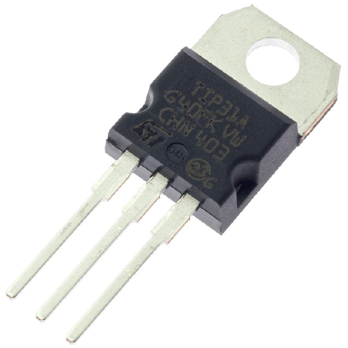
North edge (input, bit width 1) The component's gate input. Pins (assuming component faces east, gate line top/left) West edge (input, bit width matches Data Bits attribute) The component's source input that will transmit to the output Is that a transistor is meant for more basic circuit designs. It has three terminals namely emitter, base and collector. A transistor consists of two PN diodes connected back to back. If the Data Bits attribute is more than 1, the gate input is stillĪ single bit, but its value is applied simultaneously to each of theĪn N-type transistor behaves very similarly to aĬontrolled Buffer. A transistor is an electronic component that is used in circuits to either amplify or switch electrical signals or power, allowing it to be used in a wide array of electronic devices. * If source is Z, drain is Z otherwise drain is X. When gate is 0, while an N-type transistor (which has no such circle) (indicated by a circle on the gate line) transmits The determination of transmitting or disconnectingĭepends on the type of transistor: A P-type transistor The value at source may be transmitted toĭrain or there may be no connection from source, Plate, while the N-type transistor has no such circle. Transistor is indicated by a circle connecting the gate input to its Our power transistor portfolio includes power MOSFETs, silicon carbide (SiC) MOSFETs, GaN Transistors, IGBTs and a wide range of power bipolar transistors. Transistors, with slightly different behaviors described below the P-type The gate input is drawn connected to a plate that is parallel to the Logisim draws an arrowhead to indicate the direction of flow from input to output. Input and drain output are drawn connected by a plate A transistor has two inputs, called gate and source,Īnd one output, called drain.


 0 kommentar(er)
